|
|||||||
| LEXUS 1UZ-FE Engine Swap My blood sweat and tears. It will be worth it!! |
 |
| Thread Tools |
|
#136
|
||||
|
||||
|
Yesterday I went and picked up my oil dipstick tube and the hard coolant line that extends from the waterneck to the left side of the engine to just near the coil on that side. The waterline over there is to reach over to the coolant reservoir on the LS400 but I capped it off at the end over there. I decided to just use it because it also serves as a mounting location for the cam position sensor wire and also the wiring harness from the coil over there. Who knows, I might even use a coolant reservoir someday if I need to.

|
|
#137
 04-24-2009, 08:49 PM
|
||||
|
||||
|
Ok and back to the wiring! Time to get the book out while I separate wires from the harness that I won't be using. I think I need this one though! Cam position sensor wires and speed sensor but there is also a blue wire... maybe for the ignition noise suppressor? I dunno yet.
|
|
#138
04-24-2009, 08:52 PM
|
||||
|
||||
|
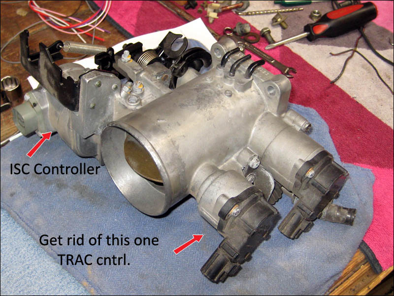
This is the connector for the optional TRAC - traction control - secondary throttle control in the throttle body. I'll be removing it from the TB and welding the pivot holes closed. So this connector and wires are tossed aside. What stinks is that they used the exact same wire and shielding as the speed sensor and cam position sensors. Why would they do this? The come from opposite sides of the engine but still what a pain in the neck.
|
|
#139
04-24-2009, 08:55 PM
|
||||
|
||||
|
Things are looking better and better. Here I have looped the fuel injector wires on the right behind the heater hose and to the left of that I looped the wires that come from the front of the right side of the engine (water temp, cold start injector timer solenoid, left side coil, etc). In my hand are some ground wires and grouped positive wires for different functions.

|
|
#140
04-24-2009, 09:00 PM
|
||||
|
||||
|
Here is a very interesting and important connector. It goes to the starter circuit which also throws out a signal to the cold start injector and it's timing solenoid. This activates the cold start injector while you are cranking the engine. Pretty interesting design. I'm wiring it in the system just incase I will need this to start my engine. I have noted that some stand alone engine computers boost the fuel from the injectors during startup so that the cold start injector isn't needed. Well I'll leave it disconnected and find out how things work later. BUT you need to run the fuel and the wiring harness like normal just incase you need it in the future. It's VERY difficult to change these parts out or even disconnect them as it requires the removal of the intake manifold.
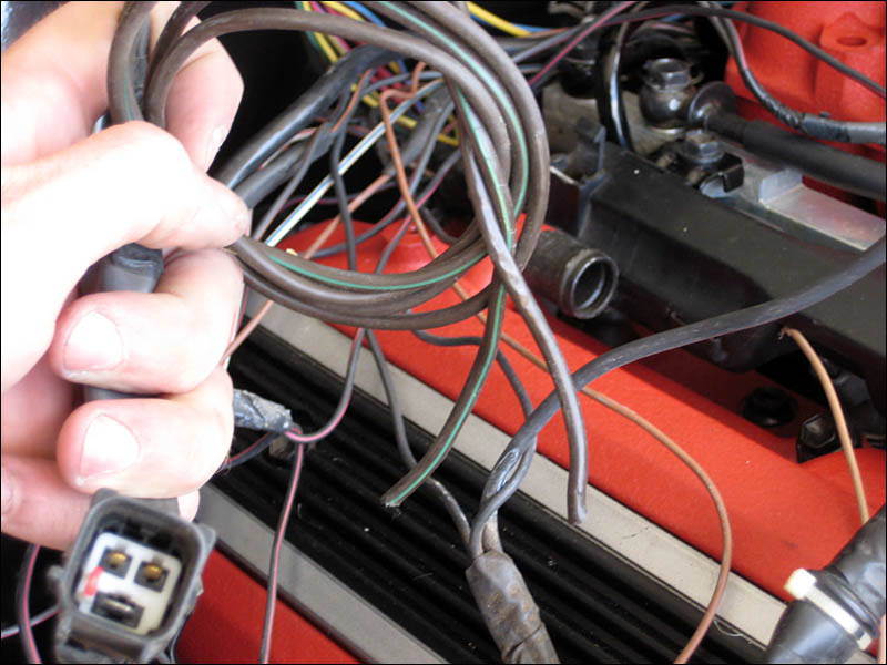 OH and also 2 of the 3 wires are for the left and right knock sensors. Don't forget those!
|
|
#141
04-24-2009, 09:04 PM
|
||||
|
||||
|
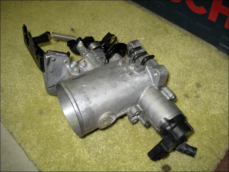
And here is where I'm leaving off for today. I have most of the wires grouped up nicely and the TB and ISC water lines were deleted. I did hook up the ISC water line to the rear waterbridge but was informed that it was purely for emissions. So I deleted it. The only water line that is hooked up is the short one to the ISC from the front water neck. I simply forgot to remove it and cap it off. But both water line inlets on either side of the ISC were capped off so I'm not concerned. I just really didn't want the hot water line running from the front ISC to the rear waterbridge along side the fuel rail and intake manifold.
|
|
#142
05-04-2009, 10:43 PM
|
||||
|
||||
|
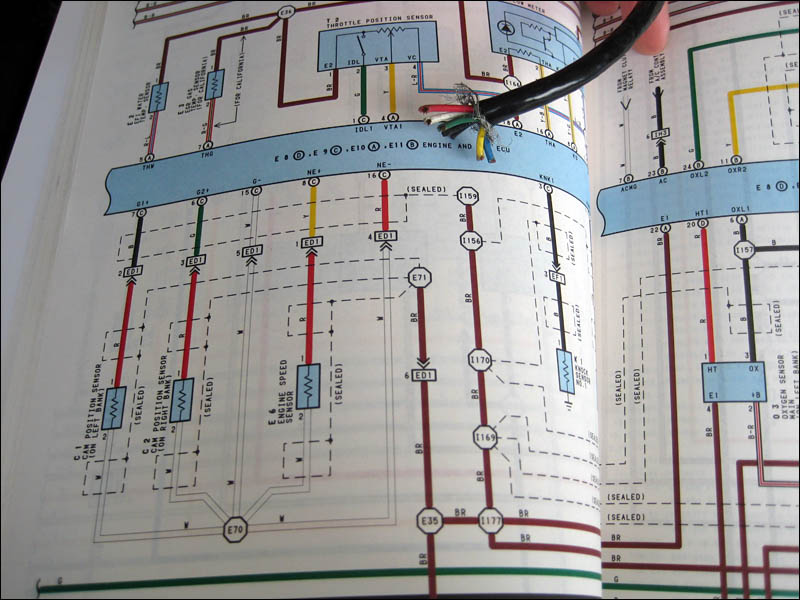
Here we go guys and gals! Most people's worst nightmare some true. I made up some pinout sheets and got busy today. I wouldn't recommend most people try this without the Lexus wiring manual on hand. What looks like secret code is explained thoroughly in the factory manual.
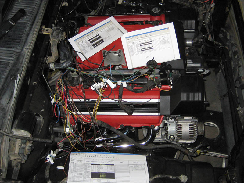 The black boxes are EGR system type wires.. you know what I'm doing with those of course. And a few of the other wires are ignition circuit and won't be going to the Adaptronic. Here I'm marking off all the wires to make sure I didn't leave anything out. Taking notes is KEY to being able to distinguish exactly what circuit you are splicing. I took pictures and made notes so that there won't be ANY questions when it comes to what I'm doing with any particular wire.
|
|
#143
05-04-2009, 11:03 PM
|
||||
|
||||
|
More fun with wiring...
Here is every single wire tagged and ready for tomorrow. There are a lot of grounds coming together all over the place. Individual sensors use grounds as well as every injector. A couple of them are sealed grounds which isn't any big deal but you have to be on the lookout for every one of them as they look different sometimes. 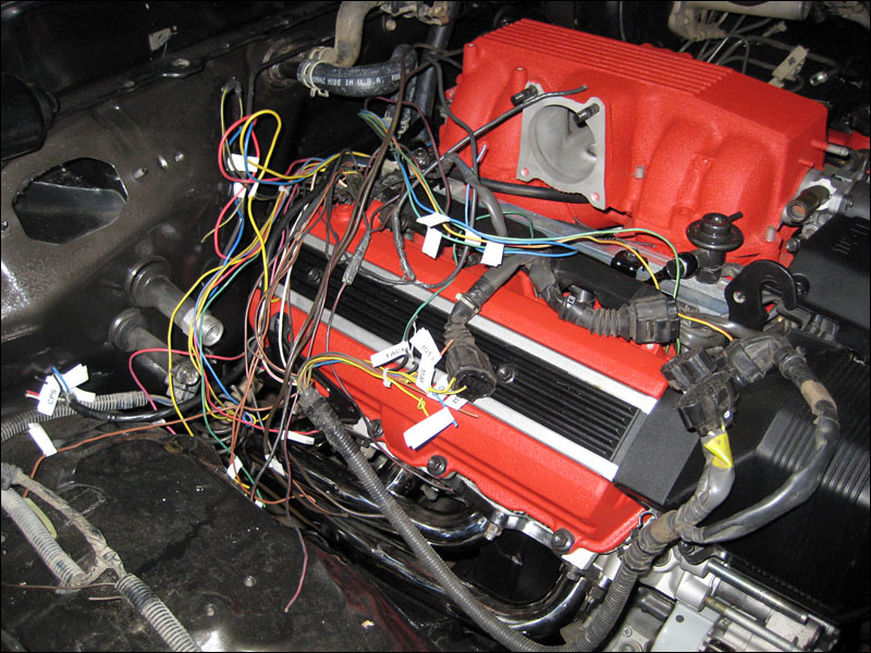 You can kinda get the feeling for which bundles of wires come from what part of the engine. You got the ignitor and MAF wires together... the ISC wires.. injector wires... crank angle and speed sensor wires... etc etc. SO that's about it for now. Tomorrow I'll just connect the wires to the Adaptronic loom and that's all I have to do with the engine wiring. Then I'll connect the alternator wiring so the chassis harness and that will take care of that. Then to plug in my laptop and fire up the computer for initialization and such. Then I'll be mounting the ignitors, cleaning up the chassis harness and fuse box mounting. Then the throttle body will be attached and the radiator mounted. Then all that's left is making my intake system and finishing up the exhaust.
|
|
#145
05-25-2009, 10:05 PM
|
||||
|
||||
|
Hey I'm doing pretty damn good on 'er. I got kidnapped for a weekend of riding with a Kawasaki motorcycle club over the weekend. But today I got back on the engine wiring. It's hard to make progress with curious neighbors getting antsy to see it run. And the occasional friend drives by just to see if I'm working with the garage open so they can stop and talk. :P
But I identified more wires and started splicing in the chassis wiring harness and starting circuit. Part of that process involved cleaning the dirty Tacoma wiring so that's a lot of fun. All of the ground wires coming together are a pain in the butt. They are a tangled and un-equal length mess from the factory so I had to redo some of those to maintain my sanity. Here are a few pictures and things are moving along. Tomorrow will see more progress as well. Not very many wires left! 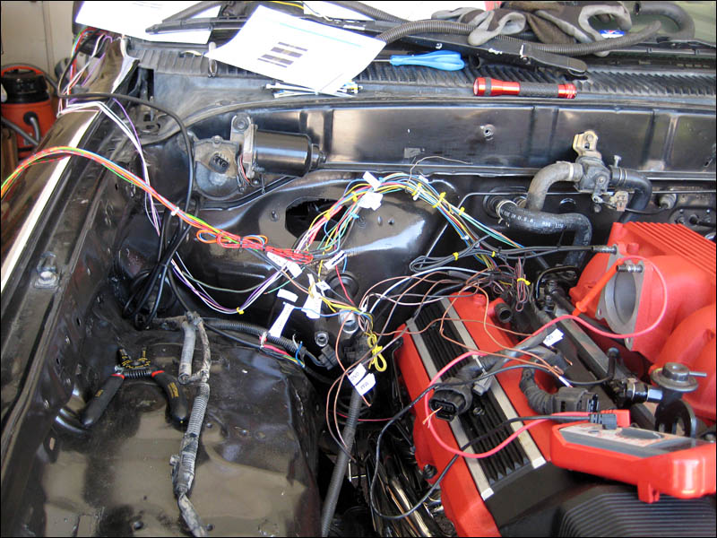 And the headbone's connected to the, neckbone... 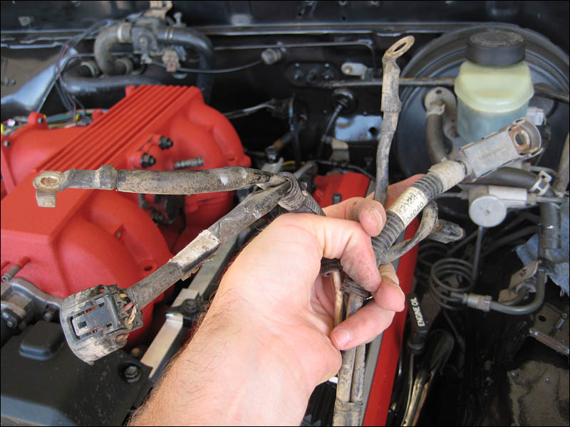
|
|
#146
05-25-2009, 10:18 PM
|
||||
|
||||
|
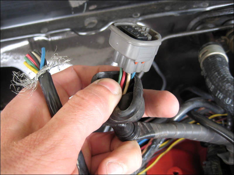
Here is just one of the hundreds of electrical mods along the way while hooking up this Adaptronic ECU. These particular pins have to do with cam position sensor wires which have to be arranged according to whether the factory ECU will be used along with the Adaptronic or if the Adaptronic will be handling the business directly. It can be done both ways. In my case I tossed out the factory computer.
 Arranging some pins in the 16 pin plug. 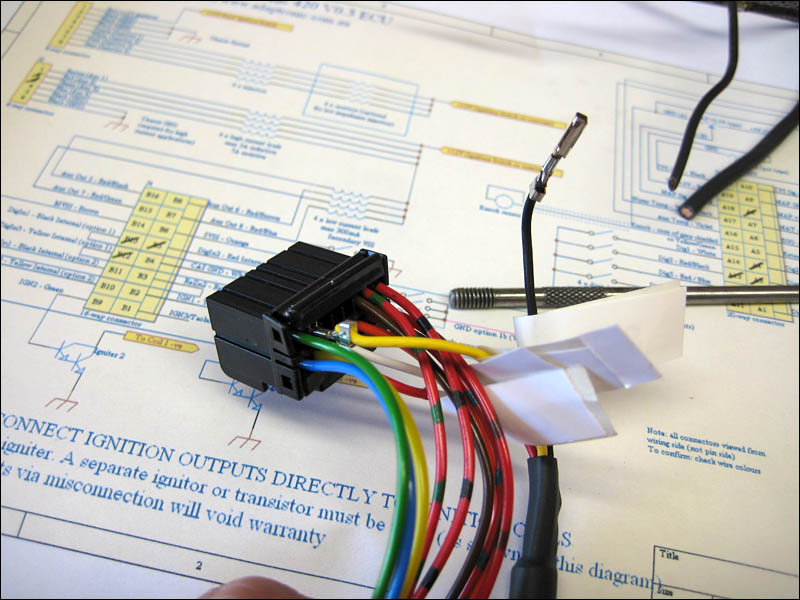
|
|
#149
06-08-2009, 02:15 PM
|
||||
|
||||
|
Then I went ahead and cleaned up some more wiring. I just decided to unwrap the injector and sensor wiring that goes along each fuel rail. I liked the stock wire protection but it's just bulky and it had dirt in it. I figured I might as well unwrap the wires and made sure that they were all going where they were supposed to. There are a couple different brands of wire wrap that look really clean so I'll decide on which one to wrap them back up with but for now zip ties will do juuust fine.
|
|
#150
06-15-2009, 10:03 PM
|
||||
|
||||
|
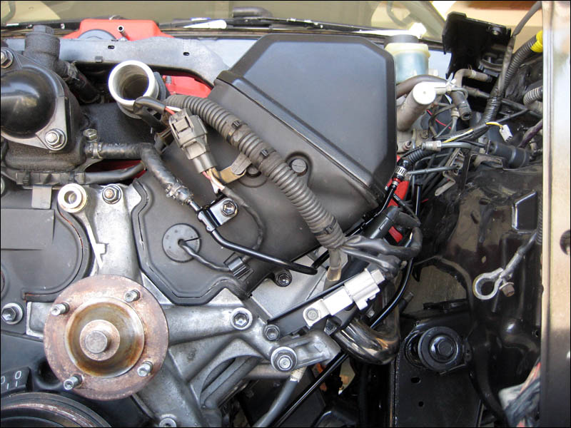
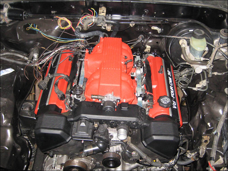
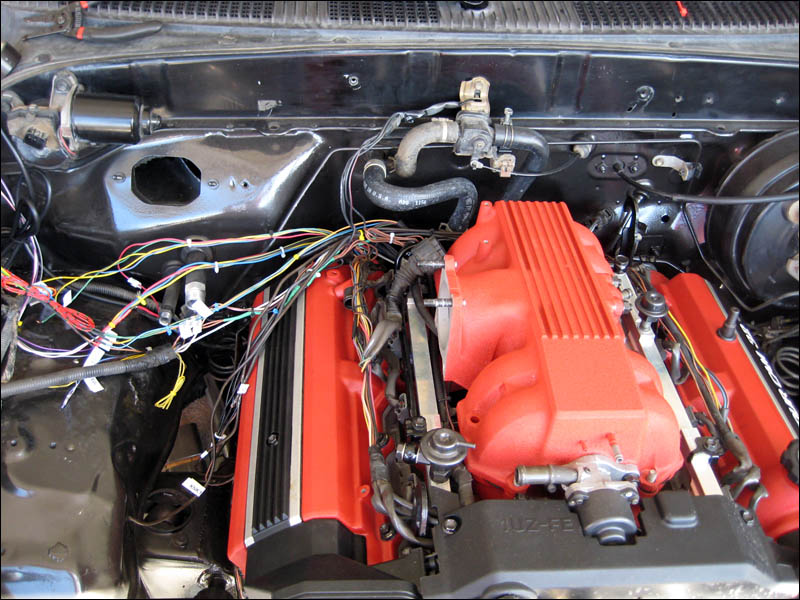
I've been putting the finishing touched on the wiring. The main thing was adapting the Lexus alternator and sensor wiring to the Tacoma chassis fuse box. This allows the Lexus alternator to power the whole truck and charge the battery as well. I'll be adding more details on this in the near future. Here is a more recent picture for now.
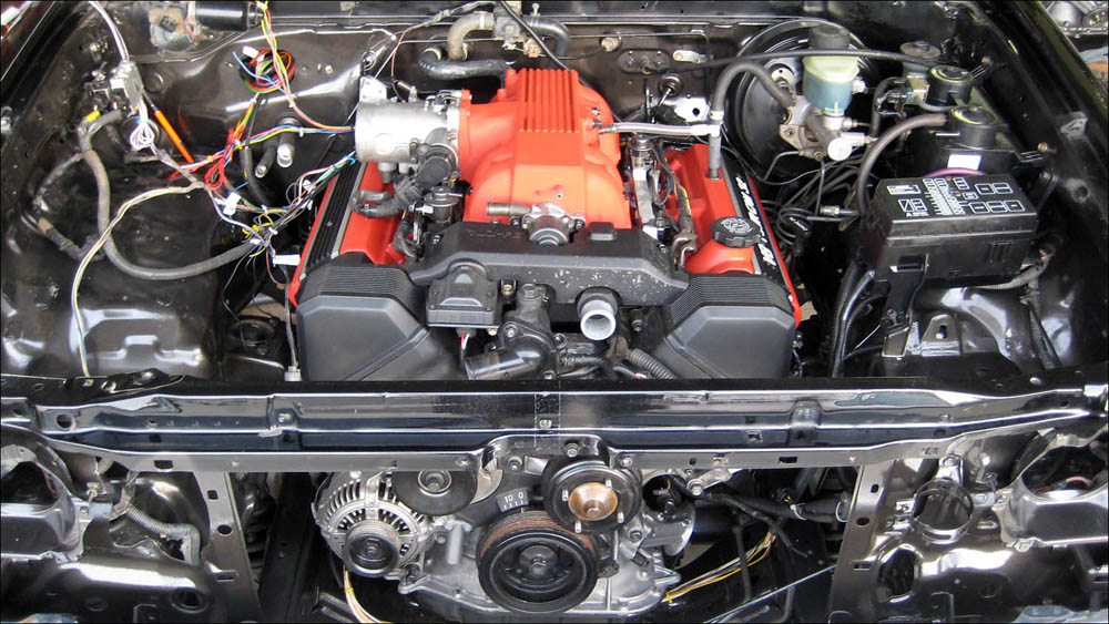 Since the picture I have installed the AC pump and the power steering pump. Then this afternoon I installed the serpentine belt so it looks like a real live engine now, ready to fire up. In the next picture you can see all the Lexus wires wrapped up in some flexible sheething and routing into the Toyota fuse box. I spent about as much time cleaning up the wires and such as I did figuring which way to wire them up. But it's done and that's all that matters. 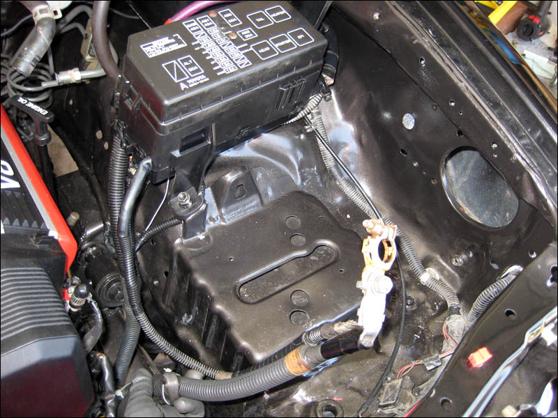
|