|
|||||||
| LEXUS 1UZ-FE Engine Swap My blood sweat and tears. It will be worth it!! |
 |
| Thread Tools |
|
#46
|
||||
|
||||
|
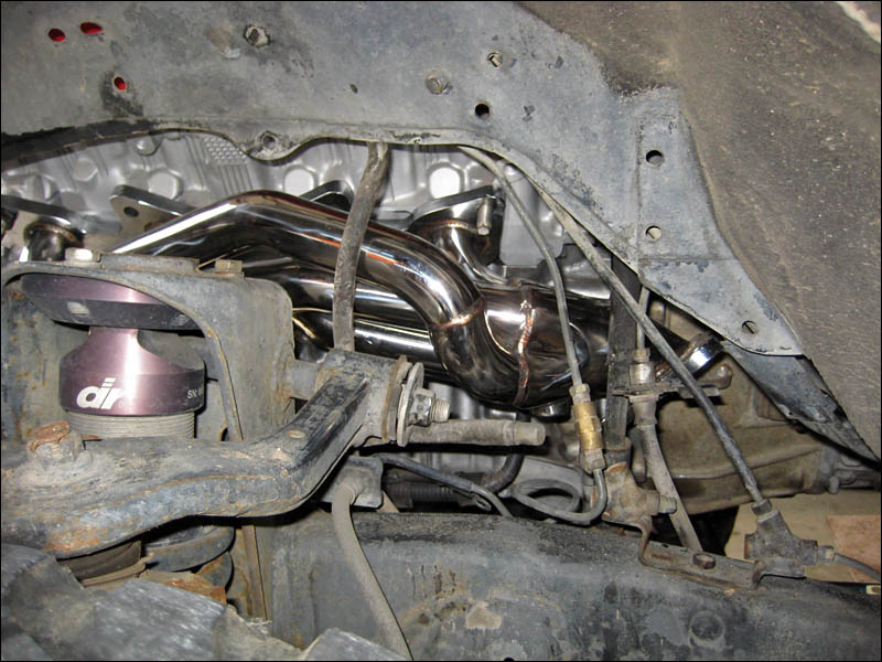
I can't WAIT to see how those headers will look by just looking under each fender from standing next to the truck. It's going to look so trick. People would just check out the grey 3RZ headers and be impressed. Now I'm going to have to keep those SS headers clean. I almost have a hard time calling them headers. I should probably be calling them shorty headers...
So anyhow I bought two cans of black Hammerite paint for the engine compartment. When I sprayed the first can out and then saw that is dried kinda dark grey (annoying) I was pretty bummed! It just didn't look right and I wanted to use the same paint on the shock towers and the frame. But since it wasn't truly black I've been racking my brain on what time of paint to try next. So get this. I break out the second can to finish up just a spot in one of the corners and it sprays BLACK! What the heck?! So today I just re-sprayed the whole engine compartment black with another coat. With the welding we did all around the engine bay it needed some touch ups anyways so it was a good thing to re-coat it and see it all in real black. Much better. 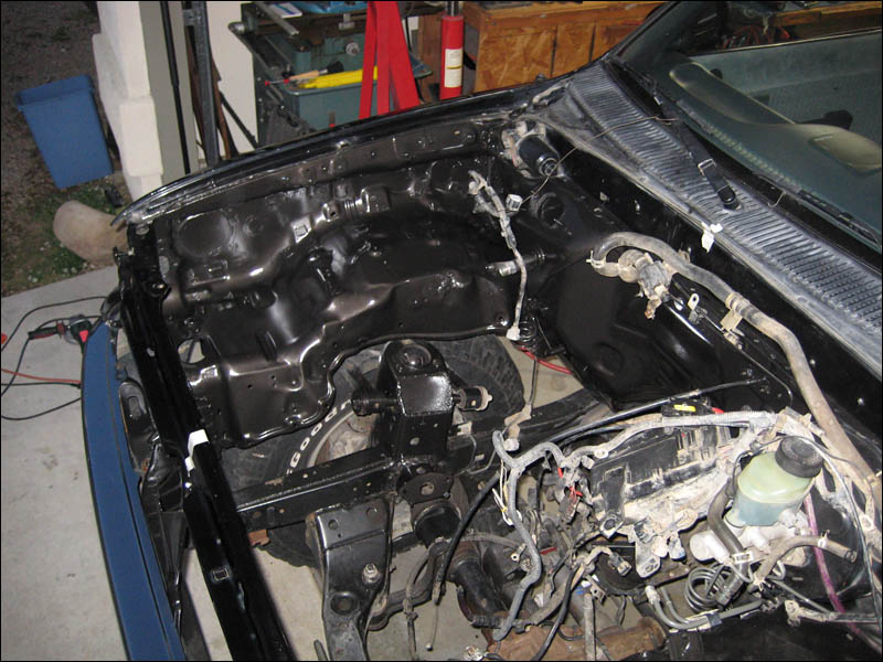

|
|
#47
 02-25-2009, 11:03 PM
|
||||
|
||||
|
I want to get shot of what the shorty headers will look like from the side of the truck but this is the only pic I have right now from when I was doing some measurements while putting the V8 in the Tacoma. I'll get a better picture when I can.
|
|
#48
02-26-2009, 07:29 PM
|
||||
|
||||
|
Ok another day gone by. I got some news on the fuel line fittings. I wanted an AN style set of connectors to integrate the factory fuel line from the drivers side fender well to connect a stainless line over to the engine and over to a banjo fitting on the fuel regulator on the rail. Well they don't have "reverse flare" AN fittings that would mate with the stock threaded coupler. They offered to machine some for me but that's so much it's ridiculous: couple hundred. Next option? Take the factory Tacoma connector to the main feeding fuel line and also the Lexus banjo fitting side of the Lexus fuel line to NAPA Auto Parts so they can use those hose ends. Use them for what? So they can make me a new fuel line. Yep some Napa stores can do this for you. I want it about 5" longer than the factory Lexus line and of course withe Toyota Tacoma coupler end on it to connect to the Tacoma fuel line. I THINK that the Lexus fuel threaded coupler is the same size and pitch as my Tacoma but the one I happen to have is acting like it's stripped and I don't care to bother trying to make it work. I have the Tacoma fuel line and that threaded end can be used much easier.
So tomorrow I should have a much more cost effective fuel line than buying the cool looking stainless fuel line with AN fittings. I don't really care how it looks and factory looking black would be better IMO. What else today? I cleaned up the Tacoma bell housing nice and almost shiny. It was pretty black but wire or mag wheel Eagle cleaner works awesome for that kind of brake dust looking dirt.
|
|
#49
03-03-2009, 03:49 PM
|
||||
|
||||
|
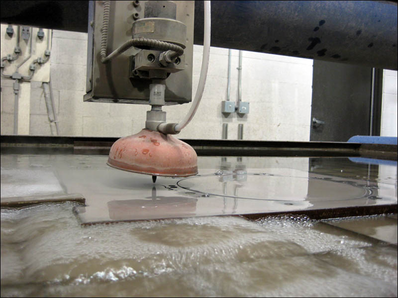
I was on hand to check out the waterjetting of my engine adapter today. Now that it's cut out it will be taken to the Bridgeport later this week for some counter-boring and cleaning up of the holes that were water cut. It's always impressive to see water and sand cut through steel so easily, so fast. It was pretty fun to watch the machine cut out this plate in less than a half hour. I am hoping that the other place will have time to machine it out in time for the weekend!
And for your viewing pleasure - I shot a quick video of the waterjet cutting out the steel plate~! Not too many people have seen a waterjet in action and I had some requests so here it is:
|
|
#50
03-04-2009, 10:05 PM
|
||||
|
||||
|
Ok here we go again with the welder.
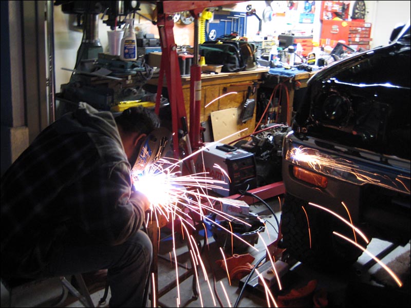 I wanted to make sure that I would have room for the steering shaft while keeping the engine centered in the frame at the same time. I might have been able to clear the steering rod but with the collar clamping down on the splines rotating so close I just decided that I should take care of this while I was waiting on my adapter. I wanted to move the collar down further and away, while at the same time eliminating the extension block that I made when I made my body lift. It worked great but it just wasn't the best solution. Every single body lift mfg. includes an extension in the Tacoma body lift kits. But extending the shaft and using a nice flex joint is really the best way to take care of the business. This new one I made is really strong as well. And without the long bolts (or additional bolts like popular body lift kits include) this is surely a better solution. I will feel much better floating over the woops in my truck with this solid steering connection. If you have a regular block of spool type extension I recommend using lock-tite, a lock nut and checking it everynow and then if you drive offroad. With this I will have no worries. Check out my newly extended lower steering shaft.  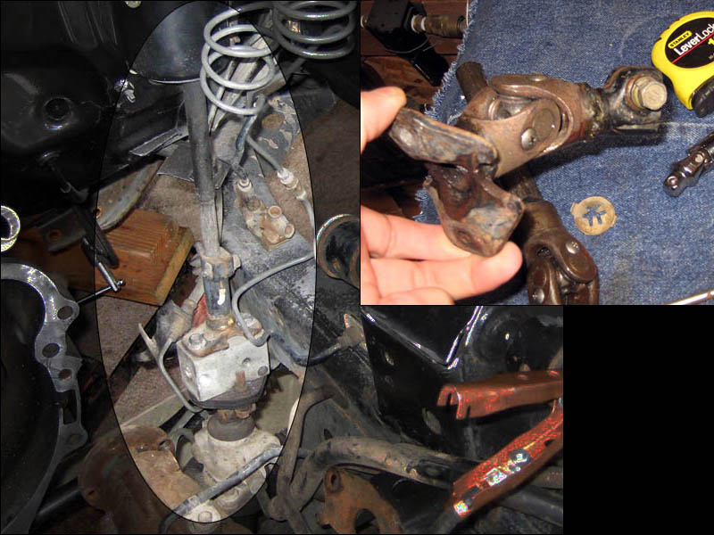
|
|
#51
03-07-2009, 10:32 PM
|
||||
|
||||
|
Yesterday and today were really busy to say the least! Adapter = DONE. I picked it up later on yesterday and immediately made a B-Line straight to Powder Coat USA to have my friends process it with any possible parts that were also being coated. Luck was on my side as they were getting ready to shoot pearl black. Perfect! So this morning I had my adapter in my hot little hands all shiny and ready to work with. Finding the bolts took a few minutes and I had to grind the heads down a little to be nearly flush with the adapter. They adapter was counter bored a good amount but only so much just to be safe. I would rather have a stronger mounting surface and machine my bellhousing a little bit to allow for spacing for the bolt heads.
Have a look at my snazzy vertical mill being put to good use! I removed the most material for the pinion gear that protrudes out from the starter motor when it is engaged. I only wanted to remove a minimal amount just to make sure there wasn't much room for any dirt to drop down in the gaps. I have some ideas for ways to cover up these gaps in the future but that's the last thing on my list as of now. Keep in mind that this is the BELLHOUSING for the W59 transmission. The starter on the 3RZ engine is located off to the side of the engine and here's a tip: the transmission output shaft isn't exactly the center of the bell housing "circle". It's not even a damn circle. 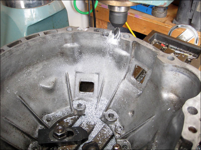 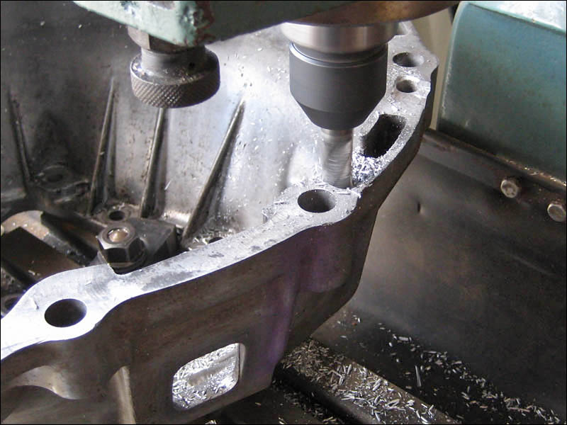
|
|
#53
03-07-2009, 10:45 PM
|
||||
|
||||
|
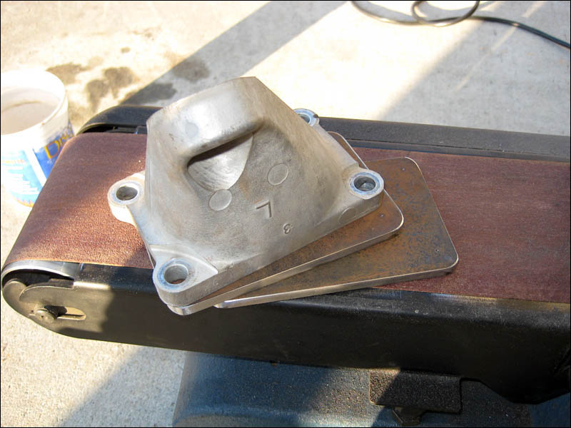
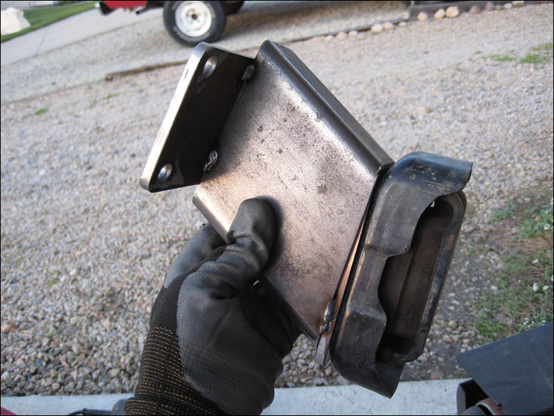
Let's move on shall we? Time for engine mount fabrication fun time. I have my handy old engine mounts that make for some great templates for new engine plates. Made my life easy. And if you look closely I transfer punched the hole locations for some drilling. A little belt sanding and they are looking perfect.
|
|
#54
03-07-2009, 10:51 PM
|
||||
|
||||
|
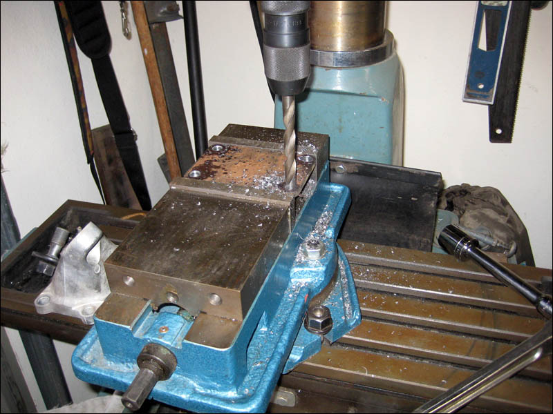
More horizontal milling, my favorite thing. I started 3 stage drilling these holes and finished the rest 2 stage. If you just use one bit the hole won't be what it should and you'll have a lot of flaring out on the backside. Use 2 bits with holes this size or risk the bit grabbing at the end which is just a nightmare.
 Plates are all cut out and tomorrow the Sawzall is going to get a workout on the square tubing I have waiting. Then some welding and with that I'll have more stuff ready to have powder coated on Monday morning. Getting carried away with all this steel work, I want to start fabbin some roll cage materials but I must concentrate on the engine of course.
|
|
#55
03-08-2009, 08:36 PM
|
||||
|
||||
|
Yay today was boring and involved a bunch of jumping up and down and all around the truck measuring 200 times. It took just as long to center the engine and transmission with proper clearance as it did to make my driver's side engine mount! Well not counting making the upper and lower mounting plate.
The tools of the trade: 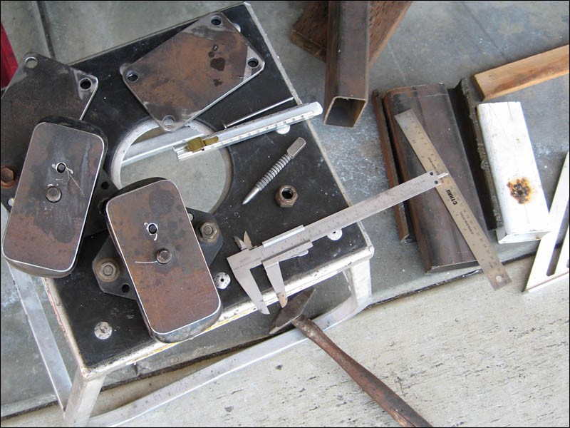
|
|
#56
03-08-2009, 08:47 PM
|
||||
|
||||
|
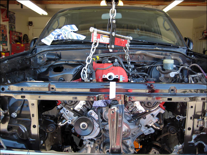
Now with the engine SURELY centered in the engine bay I could begin the measuring and head scratching. There are even more exact marks on the tape that I placed on the center lines of the engine bay front and back. Using a jack under the transmission I got the tranny/engine assembly in at the angle that I think is just right. The engine is a little nose up as I like the transmission output shaft to not stress the universal joint with more of an angle than it has to. It's just right.
|
|
#57
03-08-2009, 08:56 PM
|
||||
|
||||
|
After a couple of minutes measuring with some aluminum angled strips I was able to translate the angles I needed right to the steel. The rectangle tubing makes it easy. I wish I had a bandsaw of some kind but a grinder with a cutting wheel worked nearly as quickly. After cutting a straight line the belt sander quickly makes the lines even more exact.
 The engine mount plate is removable still. There is a hole cut in the engine side mount plate that allows a socket extension to reach inside to connect the mount to the Toyota engine mount. I was able to keep the tubing just to the inside of the engine mount plate so that the engine bolts could be fastened. It was a little tricky and there is no way I could have described what I was about to do until I actually did it. I measured and cut the passenger side as well and tomorrow I'll tack weld it and see how the engine likes to sit in between them. Then I'll put take a look at the hood and make sure it shuts! 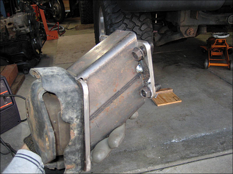
|
|
#58
03-08-2009, 09:12 PM
|
||||
|
||||
|
With how beefy the engine mounts came out that I made I really want to redo the factory Toyota Tacoma mounts. They look so flimsy and the factory bends just look like they are bent from me beating on it in the past. But they are aligned with the engine so they aren't bent. Sometime when I break out the chromoly tubing and get busy on the truck I'll redo the engine mounts with some poly engine mount pads instead of the stock rubber pads. By that time I'll probably want to make some changes anyway.
|
|
#59
03-08-2009, 09:22 PM
|
||||
|
||||
|
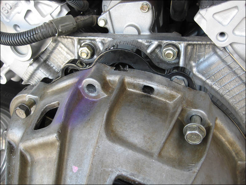
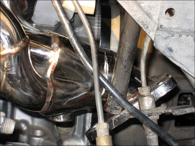
And after all that work the steering shaft still is interfering with the headers. But I had to get the engine exactly where I want it before I could make any decisions on where to start cutting. The last thing I did was take the header to a friends little shop to see if he wanted to chip in with some header mods for me. We chopped the header end off right in front of the collector and tomorrow he'll bring me some radius'd cuts for me to tack weld where I want them in order for clearance. I'll be moving the flange in towards the engine obviously and extending the section between the collector and the flange. It's another half of a day but it will be done with plenty of clearance on all sides with no interference while under heavy use. The steering shaft is kinda important after all.
") 
|
|
#60
03-09-2009, 09:43 PM
|
||||
|
||||
|
Keeping in the tradition of posting everything I do everyday here are a couple pictures of the finished dimensions of the engine mounts. This morning I just had to adjust the passenger side pieces and tack them together. I then double checked everything and went ahead and welded them together, project overkill style. The ears that these mount to on the frame will surely fold or crumble way before these will show any signs of fatigue.
The confusing angle  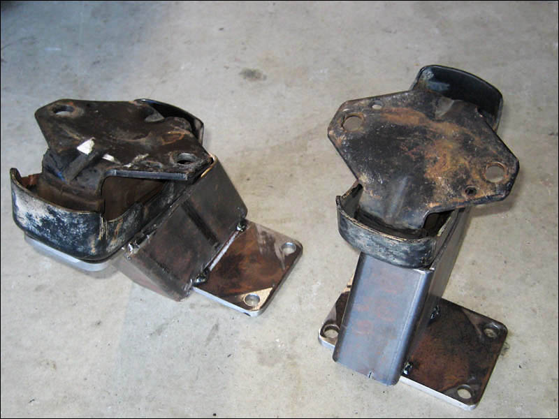
|