Work resumed today on the 1940 Hallicrafters radio. I replaced the 4 remaining original 600 volt capacitors, the last of the original components to replace. I still have some speaker wiring to do, but I was getting close to the initial power-up testing. Since these radios use high voltages and a lot of crisscrossing bare wires, I carefully inspected the components and all connections with my magnifying visor to ensure that there were no crossed connections that could create a short circuit.
For the initial testing of vintage electronics, it's best to gradually increase voltage instead of simply switching it on. If a component is connected improperly, or if a short circuit exists, it could overhead and create a fire quickly. If an electrolytic capacitor is connected backwards, it can easily explode. To avoid these problems, professional restorers use a device called a variac to gradually turn up voltage. Since this may be my only electronics restoration project, I didn't want to invest in a variac, so I built the "poor-man's Variac" - a
Dim Bulb Tester.
A
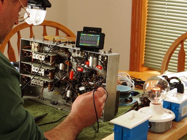
Dim Bulb Tester simply places an incandescent bulb in series with the circuit load. This reduces the current to the device being tested. If a short circuit exists in the radio, the bulb would burn brightly, and the tester could be quickly switched off before damage occurs. Testing begins with low wattage bulbs, gradually increasing the wattage of the bulb until the radio is at full voltage. You can see my Dim Bulb Tester in the picture below, to my right.
So far, there are no explosions or fires to report. I'm still in the process of validating the various output voltages from the transformer. Tomorrow I should be ready to place the first tube into the radio, the rectifier tube. Like the rectifiers in our motorcycles, this tube converts the AC to DC. If the DC voltage from this tube is within spec, more tubes will be added. I'm still likely a few weeks from connecting an antenna wire to test for sound, but I'm in no hurry.
Below is a pic of the initial power-up testing, with the dim bulb tester to my right and my pocket oscilloscope above the radio.